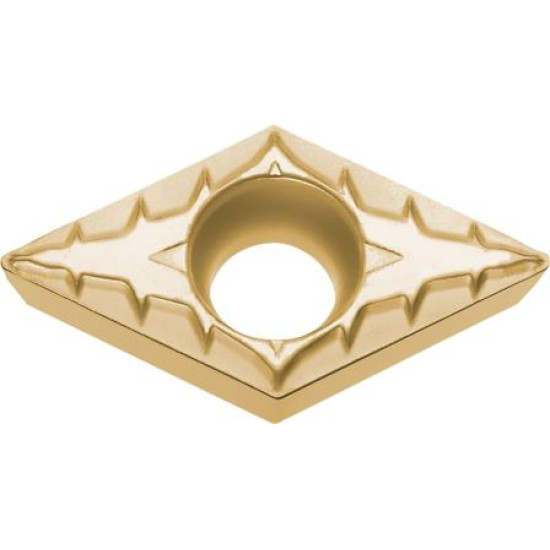
Kyocera DCMT070202
For your absolute peace of mind, all transactions are processed through and secured by PayPal. Your purchase is fully covered by PayPal Buyer Protection, ensuring secure data encryption and trusted dispute resolution.
安心の決済保護:すべてのお手続きはPayPalを介して安全に暗号化され、バイヤープロテクション(購入者保護)が適用されます。
- Stock: In Stock
- Model: KPD001
- Weight: 0.10kg
- Manufactured: In Japan
- Ships: Worldwide
- Item Code: TBR02002

Flat $50 USD Shipping worldwide via DHL Express. Maximize your savings by ordering in bulk packs!
International Shipping Note
Please note that any local customs duties, taxes, or import fees are not included in the checkout price and must be borne by the customer.
How it works: Once your package arrives at your country's customs office, DHL will contact you directly via email, SMS, or phone to guide you through the local clearance and payment process.
DHL secure global delivery. Tracked from our door to yours. Kyotow.com Secured
1. Product Overview
The Kyocera DCMT070202 is a precision indexable turning insert engineered by Kyocera in Japan for CNC lathe production. Built around a Rhombic 55° geometry with a 55° corner angle, 7.75 mm cutting edge length and 6.35 mm inscribed circle, 2.38 mm thickness and a 0.2 mm nose radius, the DCMT070202 is designed for profiling & copy turning; access to shoulders and complex contours. The 7° clearance keeps cutting forces controlled while the M-class tolerance (sintered/molded general class; most common for general machining) guarantees repeatable indexing accuracy.
2. Engineering Quick Reference
| Parameter | Specification |
|---|---|
| Full Product Name | Kyocera DCMT070202 |
| ISO Ordering Code | DCMT070202 |
| Insert Shape | Rhombic 55° (55°) |
| Cutting Edge Length | 7.75 mm |
| Inscribed Circle | 6.35 mm |
| Thickness | 2.38 mm |
| Nose Radius | 0.2 mm |
3. ISO 1832 Designation — Complete Breakdown
| ISO 1832 Position | Code | Decoded Meaning |
|---|---|---|
| Position 1 — Insert Shape | D | Rhombic 55° (55° corner) |
| Position 2 — Clearance Angle | C | 7° |
| Position 3 — Tolerance Class | M | Sintered/molded general class; most common for general machining — I.C. ±0.05–0.15 (size dep.), thickness ±0.08–0.18 |
| Position 4 — Fixing / Hole | T | With hole, one countersunk face — screw mounting |
| Position 5 — Edge Length Code | 07 | 7.75 mm (I.C. 6.35 mm) |
| Position 6 — Thickness Code | 02 | 2.38 mm |
| Position 7 — Nose Radius Code | 02 | 0.2 mm |
4. Insert Geometry & Engineering Dimensions
| Parameter | Specification |
|---|---|
| Insert Shape | Rhombic 55° (55°) |
| Cutting Edge Length | 7.75 mm |
| Inscribed Circle (I.C.) | 6.35 mm |
| Insert Thickness | 2.38 mm |
| Nose Radius | 0.2 mm |
| Clearance Angle | 7° |
| Usable Cutting Edges | 2 per face |
| Edge Strength Rating | Good |
| Fixing | With hole, one countersunk face — screw mounting |
| Geometry Tolerance | I.C. ±0.05–0.15 (size dep.), thickness ±0.08–0.18 |
5. Grade Technology — Substrate & Coating
| Parameter | Specification |
|---|---|
| Grade | Premium Carbide |
| Substrate | Micro-grain WC-Co tungsten carbide |
| Hardness | HRA 91.5–92.5 |
| Transverse Rupture Strength | ≈ 3,400–3,800 MPa |
6. Chipbreaker Geometry & Working Window
Standard molded geometry: Molded 3D chipbreaker optimized for stable chip curling and evacuation across the general feed range.
| Application Zone | Feed fn (mm/rev) | Depth of Cut ap (mm) |
|---|---|---|
| Finishing | 0.05–0.15 | 0.10–0.2 |
| Medium cutting | 0.05–0.12 | 0.2–0.6 |
| Roughing | 0.12–0.2 | 0.6–1.2 |
7. Depth-of-Cut Guide
| Cut Type | Recommended ap Range | Limiting Factor |
|---|---|---|
| Finishing | 0.05–0.2 mm | Surface finish / vibration |
| Medium | 0.2–0.6 mm | Chipbreaker working range |
| Roughing (max) | up to 1.2 mm (≈ 0.6 × 7.75 mm edge) | Edge length & machine power |
8. Recommended Workpiece Materials
Optimized for: steel, stainless steel, cast iron and non-ferrous alloys. Typical hardness window HB 150–300 for steels; see the cutting-condition tables for per-material parameters.
9. Application Capability Map
| Operation | Rating | Notes |
|---|---|---|
| External Turning (longitudinal) | Excellent | Primary operation |
| Facing | Excellent | Full facing capability |
| Profiling / Copy Turning | Very Good | Rhombic 55° corner access |
| Interrupted Cut | Fair | Reduce feed 20–30% |
| Internal Boring (matching bar) | Good | Positive geometry preferred |
10. Recommended Cutting Conditions — by Workpiece Material
| Workpiece Material | Vc (m/min) | fn (mm/rev) | ap (mm) | Coolant |
|---|---|---|---|---|
| Carbon Steel (S45C/C45, HB 180) | 144–206 | 0.11–0.25 | 0.8–2.8 | Wet (emulsion 6–10%) |
| Alloy Steel (SCM440/4140, HB 280) | 144–206 | 0.11–0.25 | 0.8–2.8 | Wet (emulsion 6–10%) |
| Stainless Steel (SUS304/1.4301) | 112–161 | 0.1–0.22 | 0.7–2.5 | Wet (emulsion 6–10%) |
| Gray Cast Iron (FC250/GG25) | 128–184 | 0.12–0.28 | 0.9–3.1 | Dry / MQL |
| Nodular Cast Iron (FCD450) | 128–184 | 0.12–0.28 | 0.9–3.1 | Dry / MQL |
| Heat-Resistant Alloy (Inconel 718) | 36–51 | 0.07–0.15 | 0.6–2.1 | Wet (emulsion 6–10%) |
| Titanium Alloy (Ti-6Al-4V) | 36–51 | 0.07–0.15 | 0.6–2.1 | Wet (emulsion 6–10%) |
11. Cutting Conditions — by Operation Type
| Operation | Vc factor | Feed fn (mm/rev) | DoC ap (mm) | Expected Surface Ra (µm) |
|---|---|---|---|---|
| Finishing | × 1.15 of table value | 0.05–0.07 | 0.05–0.2 | 1.6–3.1 |
| Medium | × 1.00 | 0.07–0.14 | 0.2–0.5 | 3.1–12.2 |
| Roughing | × 0.80–0.90 | 0.14–0.22 | 0.5–1 | 12.2–30.3 |
Programming note: Values assume a rigid setup with tool overhang ≤ 4× shank diameter and continuous cut. For interrupted cuts reduce feed 20–30% and Vc 10%.
12. Surface Finish vs Feed (Theoretical Ra)
| Feed fn (mm/rev) | Theoretical Ra with r=0.2 mm (µm) | Typical Operation |
|---|---|---|
| 0.05 | 1.6 | Finishing |
| 0.08 | 4.0 | Medium |
| 0.10 | 6.3 | Medium |
| 0.15 | 14.1 | Roughing |
| 0.20 | 25.0 | Roughing |
| 0.25 | 39.1 | Roughing |
| 0.30 | 56.2 | Roughing |
| 0.40 | 100.0 | Roughing |
Formula: Ra ≈ fn² / (8 × r). With the r = 0.2 mm nose radius of this insert, feeds up to 0.05 mm/rev stay in finishing territory (Ra ≤ 1.6 µm). Wiper-chipbreaker inserts allow roughly double these feeds at equal finish.
13. Edge Preparation & Wear Limits
| Wear Criterion | Limit | Action |
|---|---|---|
| Flank wear VB | 0.30 mm (finishing) / 0.50 mm (roughing) | Index to fresh corner |
| Crater depth KT | 0.10 mm | Reduce Vc 10–15% or improve coolant |
| Notch wear at DoC line | Visible notch | Vary DoC between passes; reduce Vc |
| Built-up edge | Any BUE on rake | Increase Vc; check coolant concentration |
| Chipping / plastic deformation | Edge micro-fracture or deformed nose | Reduce feed/Vc; verify rigidity; tougher grade |
14. Compatible Toolholders
ISO holders for 55° rhombic inserts. Always match the insert seat size to the holder designation.
| Compatible Holder Family | Seat Size | Mounting |
|---|---|---|
| MDJNR/L | Seat size 07 | External / Internal |
| PDJNR/L | Seat size 07 | External / Internal |
| DDJNR/L | Seat size 07 | External / Internal |
| SDJCR/L (positive boring) | Seat size 07 | External / Internal |
15. Troubleshooting Guide
| Problem | Likely Cause | Corrective Action |
|---|---|---|
| Short tool life | Vc too high / wrong grade | Reduce Vc 10–20%; select more wear-resistant grade |
| Edge chipping | Impact / vibration / feed too high at entry | Reduce feed at entry; improve rigidity; tougher grade |
| Poor surface finish | BUE, worn nose radius, feed too high | Increase Vc; reduce feed; check nose wear |
| Long stringy chips | Feed below chipbreaker window | Increase feed or DoC into chipbreaker working range |
| Vibration marks | Overhang too long / loose clamping | Shorten overhang (≤4×D); re-torque clamping screw |
| Dimension drift | Nose wear / thermal growth | Index insert; apply tool-wear compensation |
16. Operating & Handling Guidelines
- Clean the holder seat thoroughly before mounting; any chip or burr under the insert causes edge breakage
- Tighten the clamping screw to 2.0–4.0 Nm (size-dependent) with a torque wrench — never over-tighten
- Check insert seating runout ≤ 0.02 mm TIR before the first cut
- Run-in new edges at 80% Vc for the first 2–3 minutes of cut
- Index at the wear limits — do not run to catastrophic failure
- Apply coolant continuously; on/off coolant cycling causes thermal cracks
17. Quality Assurance & Manufacturing
| Quality Attribute | Specification |
|---|---|
| Manufacturing Standard | ISO 9001:2015 certified Kyocera production, Japan |
| Dimensional Inspection | 100% inspection with CMM-class tolerance control |
| Edge Inspection | Microscopic cutting-edge inspection on every piece |
| Traceability | Laser-marked lot code on packaging; full batch traceability |
| Country of Origin | Japan |
18. Packaging & Ordering Information
| Parameter | Specification |
|---|---|
| Manufacturer Part Number | See product name |
| Ordering Code | DCMT070202 |
| Standard Packaging | 10 inserts per box (plastic case with individual pockets) |
| Minimum Order Quantity | 1 box (10 pcs) |
| Stock Status | In stock — ships within 1–3 business days |
| Warranty | 90-day manufacturing-defect warranty |
19. Catalog Meta Data
| Parameter | Specification |
|---|---|
| Brand | Kyocera |
| Product Type | Indexable Turning Insert |
| Full Product Name | Kyocera DCMT070202 |
| ISO Code | DCMT070202 |
| Shape | Rhombic 55° |
| Nose Radius | 0.2 mm |
| Origin | Japan |
20. Frequently Asked Questions
Q: What materials can the DCMT070202 machine?
A: Steels, stainless steels and cast iron within its application window.
Q: What feed should I start with on the DCMT070202?
A: Start at fn ≈ 0.07 mm/rev — inside the standard chipbreaker window — and adjust toward 0.14 mm/rev for medium cutting with the r = 0.2 mm nose radius.
Q: Which toolholder fits the DCMT070202?
A: Any ISO holder with a Rhombic 55° seat in size 07 (e.g., the families listed in Section 14). Match the seat size exactly.
Q: When must I index the DCMT070202?
A: Index at VB = 0.30 mm flank wear for finishing or 0.50 mm for roughing — running beyond this risks edge collapse and workpiece damage.
Q: Is the DCMT070202 suitable for interrupted cuts?
A: Light interruptions only; reduce feed 20–30% and consider a tougher grade for heavy interruptions.
21. Engineering Support
Kyotow.com provides free application-engineering support for this insert: grade selection, cutting-parameter optimization and tool-life troubleshooting. Contact our technical desk with your workpiece material, hardness and machine specification.
Why Buy from Kyotow.com? 100% genuine OEM Kyocera cutting tools sourced through authorized channels. Full manufacturer warranty & batch traceability. Fast worldwide shipping with tracked delivery. Free engineering support for cutting parameter selection, grade choice and application troubleshooting.
✓ Genuine Kyocera Product
| Manufacturer | Kyocera Corporation |
|---|---|
| Status | Verified Original Product |
| Quality Assurance | Guaranteed Genuine Kyocera Components |
発送・在庫情報
We ship worldwide through our strategic global logistics network. Products are dispatched directly from our international distribution facilities to ensure efficient delivery and customs clearance.
-
Stock Enquiries (在庫確認):
Contact our logistics team at sales.kyotow@gmail.com for real-time inventory status and dispatch location information. -
In-Stock Items (在庫あり):
Normally dispatched within 3 business days from the nearest regional warehouse. -
Factory Procurement (取寄せ):
Manufacturing and dispatch typically require 4–5 weeks. Once production begins, cancellations cannot be accommodated. -
Authenticity Guarantee (本物保証):
All products sold by Kyotow are 100% genuine and sourced through authorized Japanese and international distribution channels.
正確な製品情報
Following the Japanese philosophy of Monozukuri (物の作り), we strive to maintain exceptional technical accuracy throughout our product catalog.
- Confirm dimensions, geometry, coating, and grade using the official Kyocera item code.
- Technical datasheets are available upon request.
- For technical clarification contact sales.kyotow@gmail.com.
返品・キャンセルポリシー
-
100% Accuracy Guarantee:
Full refund or replacement will be provided if the verified Kyocera item received differs from the official item code specified in your order confirmation. -
Order Finality:
Due to automated procurement systems connected directly to global factory distribution channels, orders cannot be modified or cancelled once processing has commenced. -
Technical Assistance:
Please verify machine compatibility, insert geometry, coating, and application grade before placing your order.
安全な決済方法
✓ Encrypted Transactions
✓ Global Buyer Protection
✓ Safe International Payments
All international payments are securely processed through PayPal, ensuring maximum transaction security and customer protection.
国際スピード郵便
✓ Full Shipment Tracking
✓ Global Logistics Network
✓ Flat Worldwide Shipping Rate: USD $50
Orders are shipped through our DHL Express corporate account from distribution facilities across Asia, Europe, and China for reliable international delivery.
Need Technical Assistance?
Contact our industrial tooling specialists for application support, tooling recommendations, datasheets, and compatibility verification.
sales.kyotow@gmail.comDirect Supply Chain Transparency サプライチェーンの透明性
Why are our prices so low? (価格が安い理由): Kyotow sources genuine Kyocera tools directly from domestic Japanese distribution networks, completely bypassing the steep regional markups, localized sales overhead, and heavy middleman margins of Western distributors. We pass 100% of those structural savings directly to your machine shop.
Kyotowは日本の国内流通ネットワークから京セラ正規品を直接仕入れることで、欧米の現地代理店による大幅な上乗せ価格や営業コスト、中間マージンを完全に排除しています。その構造的メリットを、お客様の加工現場へ100%還元いたします。
Domestic Sourced
Procured straight from Japan's local wholesale networks to capture maximum market arbitrage.
100% Genuine
Zero counterfeit risk. All items are brand-new, authentic factory-sealed Japanese stock.
No Regional Markups
We bypass Western corporate sales teams and localized regional overhead costs entirely.